 DE
DE  EN
EN 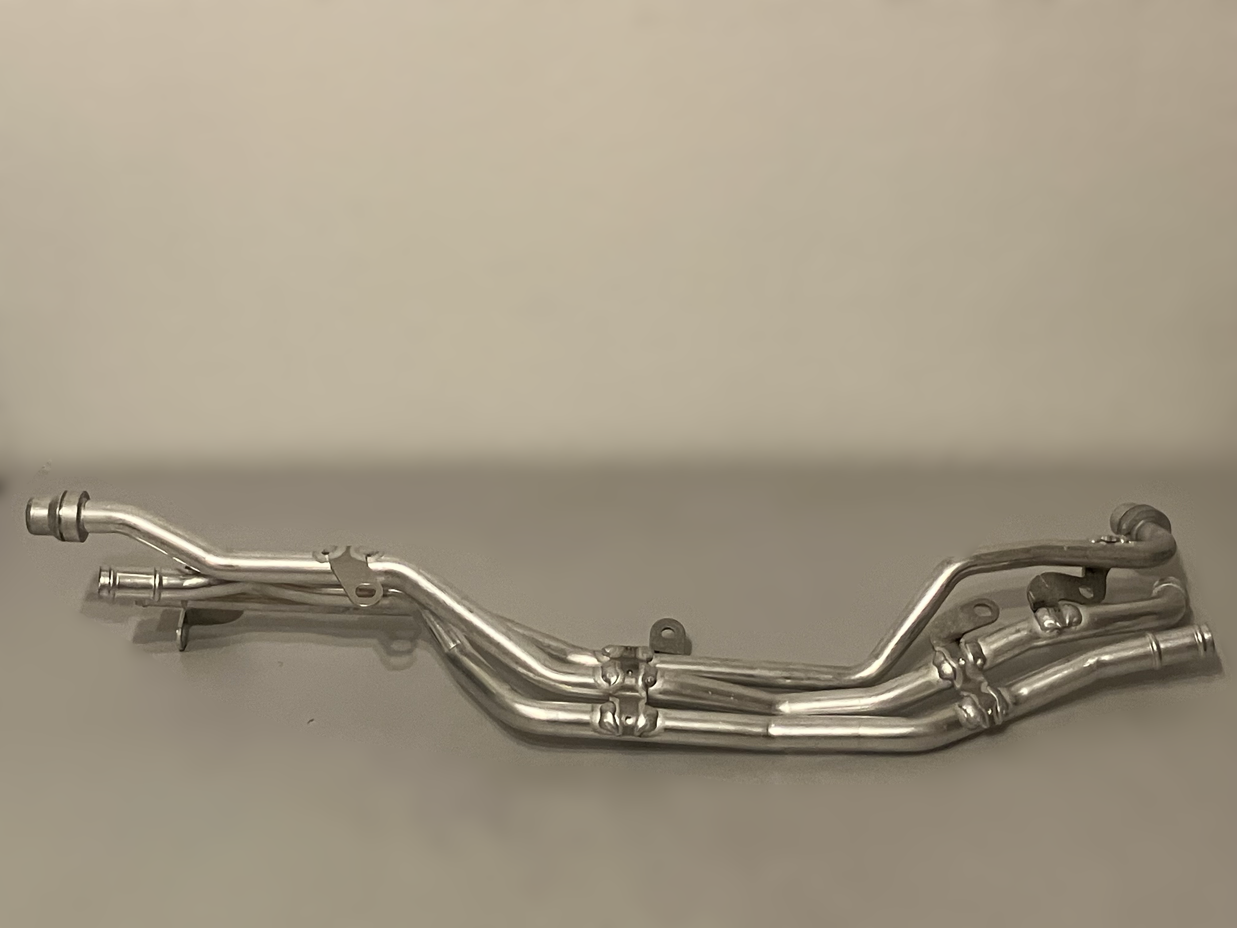
With a special camera system that works exclusively with visible light, the 3D surface of a component can be captured in seconds.
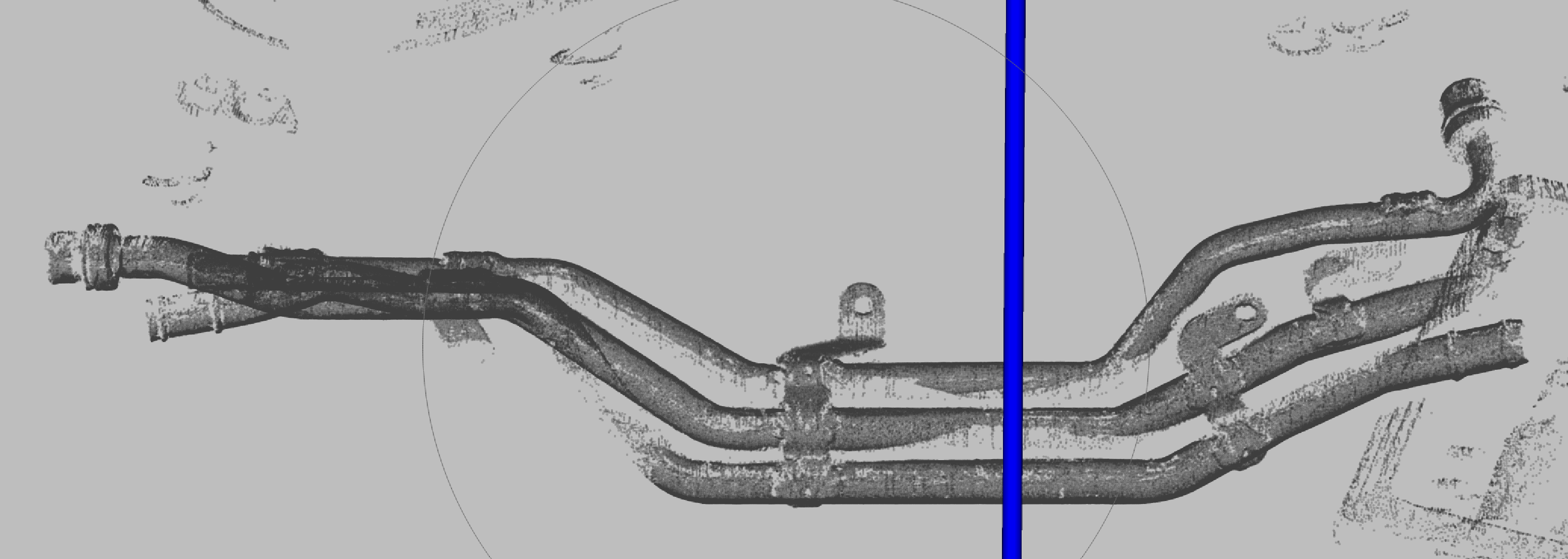
Within milliseconds, the data is processed by the JL Tube, and a comparison between actual and target values (Ist-Soll comparison) of your form and positional tolerances is performed for the entire component.
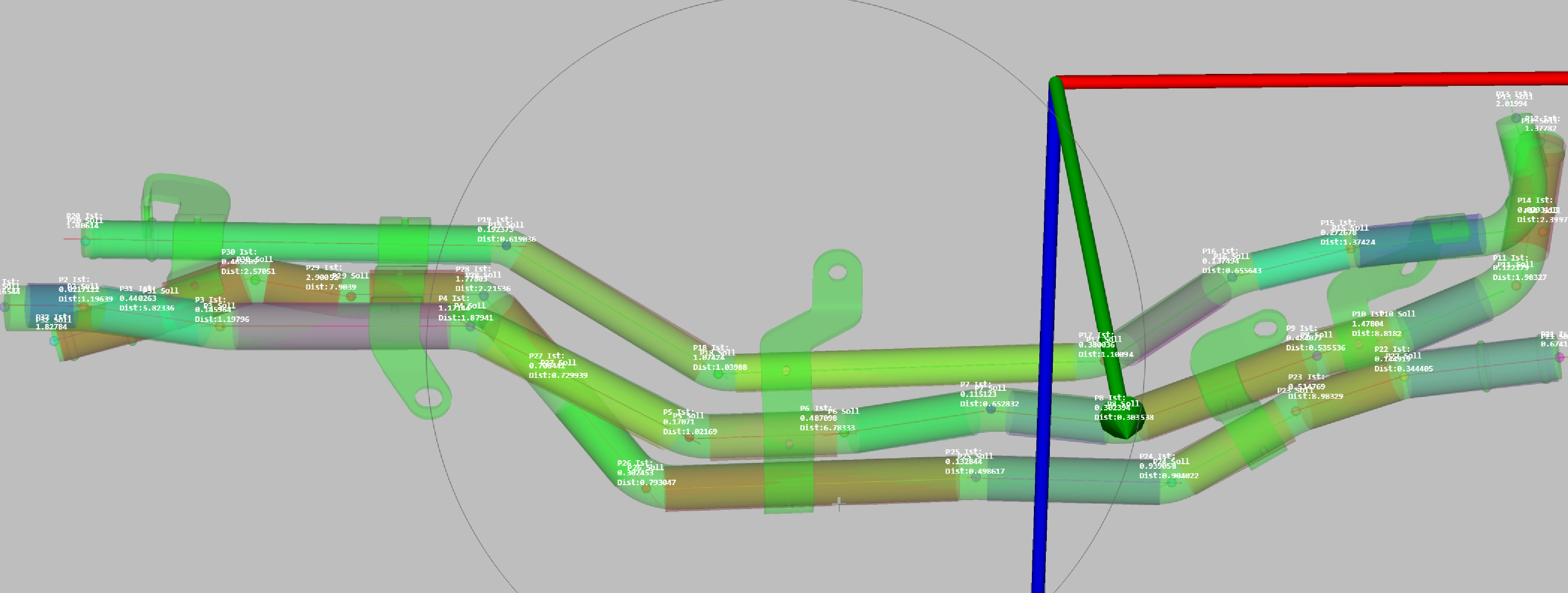
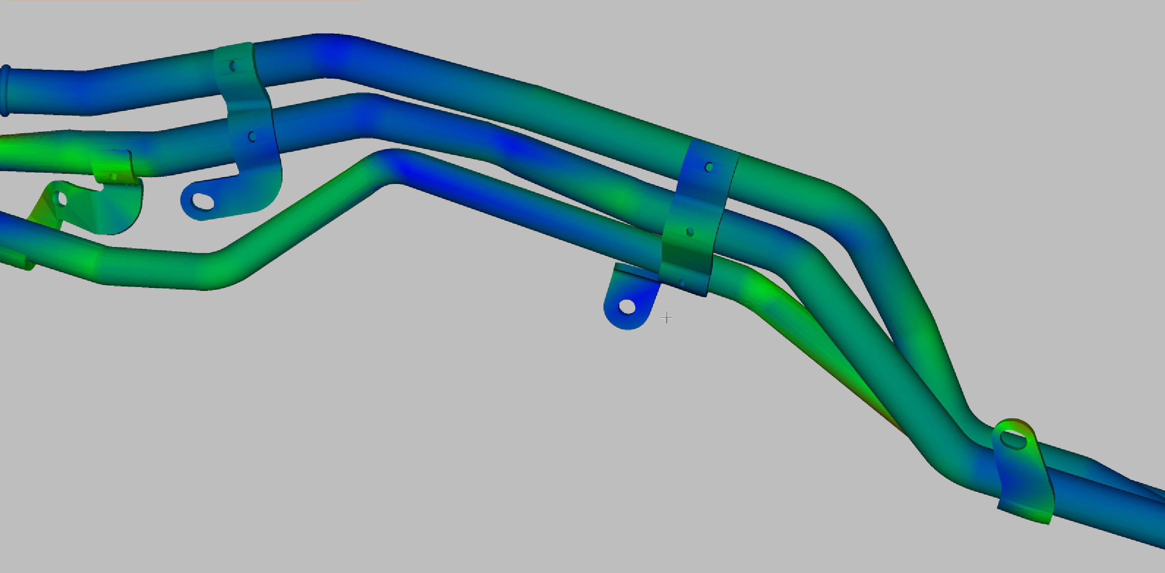
The position of the support brackets can also be calculated relative to the tube path and attached elements (e.g., valves, sensors, T-pieces, dampers, clips, labels, etc.). The result is aligned with the dimensions of the coordinate system in your customer's design drawing.
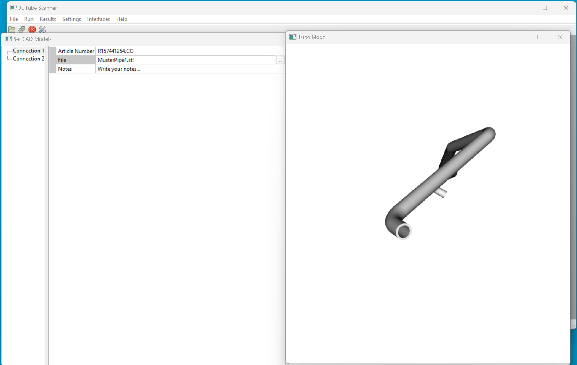
With the graphical user interface of JL-Automation, you can configure the target values and tolerances of the tube path as well as the target positions of the mounted elements.
For each measurement, the system provides the XYZ deviation values between the target and actual values.
Additionally, you will receive a measurement protocol that you can print for your documentation.